A New Approach to Volumetric displays
Michel David
Inventor
Abstract
This document propose is to describe the working principle and apparatus for a new type of volumetric displays. Using new sets of geometrical assumptions and open source building methods, these volumetric displays are simpler and cheaper to construct, therefore highly potential to contribute to the widespread of volumetric displays in the upcoming future.
This work includes a description of a proof-of-concept prototype and intendeds to become the guideline for an open source platform, for developing and contributing to the advancement of volumetric displays technology.
Introduction
like so many inventions, Volumetric displays have been around for many years. First appearing as abstracted devices in Science fiction literature, and then developing into working devices with the evolution of computers towards the last third of the 20th century.
There is general agreement that volumetric displays have not reached their technological maturity and requires further development to become an everyday device used by the general public.
Fig.1 – General view of volumetric display prototype
Operation principle
Projection surface / Screen
This volumetric display is of the “volume sweeping” type, using a rotating Helicoidal projection surface. There are similar systems described both in patents and operational devices, like the Felix 3D Display or US patent 5,854,613 (Laser based 3D volumetric display system) using a variety of
helicoids for projections.
In this volumetric display a double helicoid projection surface (Fig.3) was chosen for its structural stability and balance properties.
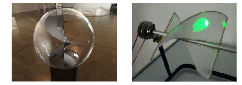 Fig.2 – Single helicoid projection surface Fig.3 – The chosen Double helicoid projection surface
Unlike other systems this helicoid is built from a light weight textile, stretched on metal wire-frame to create the helicoid shape. The usage of light textile material facilitate the devices mechanics and reduces vibrations and noises. It enable to use the device without a protective screen (typically made from acrylic glass) and still maintain proper safety for the user. It is important to notice that protective screens are problematic dew to their tendency to reflect light and so contaminate the optical output of the device.
Another significant advantage for using textile lies in the fact the air can flow trough it, reducing the air resistance of the helicoid to the fast rotation. This leads to smaller hardware components such as motors and bearings and eventually to lighter and cheaper devices. Choosing the right textile is crucial for proper operation of the device. I have chose to experiment with a white stretchable textile found as pantyhose in every department store. It is important that both optical and structural properties of the textile will be optimal, so that a high quality light refraction is achieved but yet the helicoid structure remains unchanged wile rotating. Other suitable textiles can be used, finding the optimal textile is subject for further research. It is important to understand that there is no mechanical limitation for the size of these screens. They can be built in a variety of sizes and can be used for creating extremely large installations and public displays.
Projection Geometry / Data
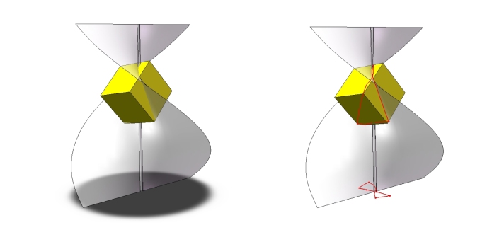
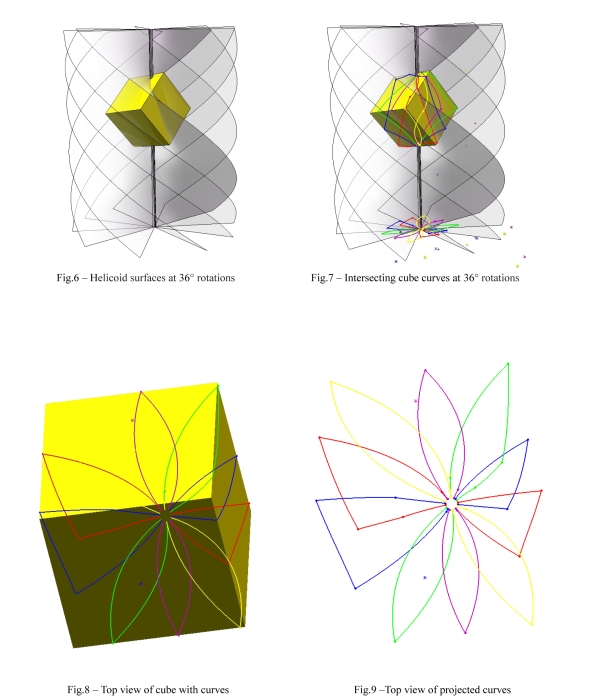
In order to represent an object in space using a projection surface, it is necessary to find the right geometry to project onto the helicoid. Ideally the projected image should be two-dimensional and be produced by simple means. In this approach a 3D model of a cube is intersecting the helicoid so that their surfaces intersection create a 3D curve (colored red – fig.5). The 3D curve is then projected onto the surface below to create the two dimensional projection image. This two-dimensional image will be later projected back on the surface, either from above or below (in the prototype it is horizontal) to recreate the 3D curve of the intersecting bodies.
Fig. 4 – Cube model and helicoid surface Fig.5 – Intersection 3D curve (above) and projected 2D image
The main assumption is that when this curve projections / images are repeated many times while the helicoid rotates an object will appear to float within the screens volume. The resolution of the system will be determine by both the 2D projected image resolution and by the number of projections for every rotation. Clearly, the greater number of projections achieved per rotation will bring to higher resolution.
In these visual examples (fig. 6-15) the curve data is excavated every 36°, so that 10 curves are produced for every full (360°) rotation of the screen.
These highly esthetic curves are the result of the mathematical intersection of simple 3D objects with a double helicoid surface. They can easily be computed and translated into 2D images (like with video projectors) or curve projections (as with laser projectors). They will be later projected back on the helicoid surface to recreate the 3D image.
Prototype and assembly
General
The prototype divides into 6 main components (Fig.16)
1. Body / Frame
2. Motor
3. Projection Surface (Screen)
4. Projection unit
5. Information disc
6. Microcontroller
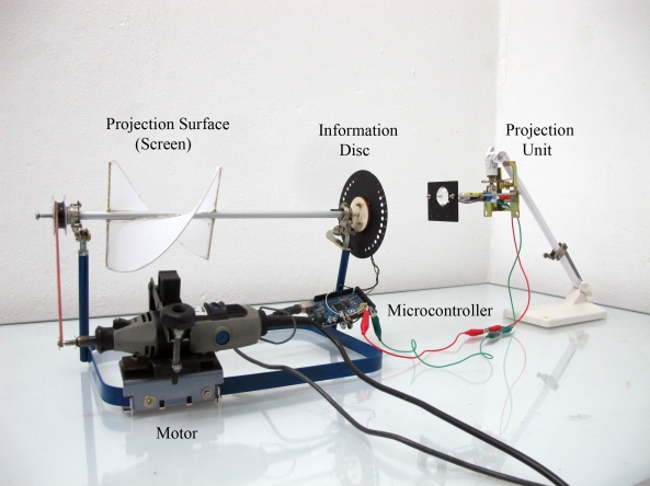
Fig.16 – General view of prototype and components
Body / Frame
The frame keeps all necessary components in their place. It supports the main axis, the axis bearings (there are two bearings in this prototype) and the motor. In this frame the axis is horizontal dew to it’s simplicity of construction, however many other possible design exist and should be further investigated.
Motor
Any motor can be used for rotating the axis as long as it is sufficiently strong and fast. The motor can also be controlled by the microcontroller, however In this prototype a simple AC motor (Dremel) was used.
Projection surface / screen
See description on page 2 of this document (Fig.2 and 3)
Projection Unit
The Projection unit is the component producing the light for the projection. It can either use normal light sources like LED’s or laser beams using diopters. The light is then projected trough the Information Disc (see Information disc) to create the desired images. Both light sources have advantages and disadvantages depending on the requited results. It is imperative to understand that every kind of projector can be used (video and laser) with this volumetric display technology. Current video projectors speed is relatively low for 3D imagery applications. An average video projector projects at a frame rate of 50-60Hz (up to 200Hz for high-end models), that is usually insufficient for producing high quality 3D imagery. Laser projectors from the other hand are much faster, working at about 60,000 points per second, but are expensive and therefore
unsuitable for this project.
In this prototype I have used two different light sources for experiment. The first was a laser diopter with a lens producing a narrow light cone. The major advantage of using laser light is that it has a large focal field (where the projected light is in focus) and need relatively
simple optics. Unfortunately the laser diopter was not able to flicker at the necessary frame rate (900-1000Hz) because of its driver electronics and was eventually replaced with an high power LED. The LED from the other hand, flickered well but produced regular light witch has a narrower focal field, leading to blurry projections on the screen.
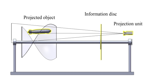
Fig.17 – Schematics of optic components
The light source method can be significantly improved and should be the subject for more Trial and error experiments.
Information Disc
The information disc is the component in charge of storing the projected object data and for timing the light flicks. At the moment the object projection data is retrieved from a CAD software (Fig.18-20), hopefully in the future it will be automatically crated by a designated open source program.
Retrieving objects data;
In this case a Zeppelin model was built and positioned within the screens volume. The intersection curves of the model with the screen creates a curve that is later projected on a plane (Fig.18 colored red and yellow respectively).
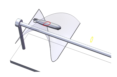
Fig.18 – Zeppelin model intersecting screen (red) and projected curve (yellow).
This process is repeated several times in order to retrieve as much geometrical information as possible. In this case, information is collected every 10° so that 36 images are presenting the object for every full rotation.
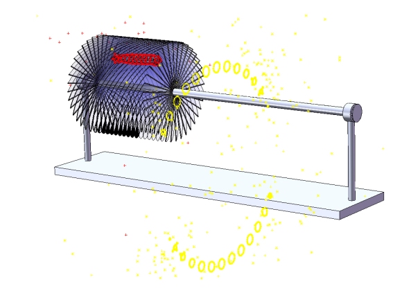
Fig.19 – Zeppelin model intersecting 10° screen rotations (red) and projected curves (yellow).
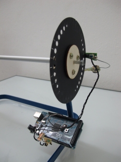
The graphic information retrieved from the CAD software is transferred to create the information disc. Timing slots, calibration marks and axis holes are added, and the disc is cut using a laser cutter.
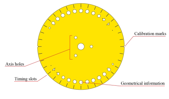
Fig.20 – Information Disc and components
Microprocessor
This volumetric display uses an Arduino microprocessor. Arduino’s are open source controllers for interface and robotic applications, they are widespread and well known to geeks worldwide. In this project the processor is used to time the light and correlate it with the changing images (like in Cinema). Timing slots on the information disk are detected by a photodiode sensor, leading the controller to pulse the light source (projection unit) accordingly.
Fig.21 – Microcontroller, photodiod sensor and information disc assembly.
Results and conclusions
Results
The prototype volumetric display has shown excellent behavior providing a coherent and stable image. Considering the relatively low resolution the projection/disc system has provided, projected objects where easily recognized and small details where visible (for example; the tail detail of the Zeppelin). See link for video: Volumetric display for 40 euros
Conclusion
This first attempt has proven many of the above assumptions. It has enabled to for the first time to build extremely cheap volumetric displays with sufficient quality, to initiate an open source platform to continue and develop these marvelous devices.
One can only hope this work will inspire others to keep and advance these technologies to the point it will become widespread. An every day tool in the hands of scientists, engineers, architects and anyone that wants to work and enjoy it.
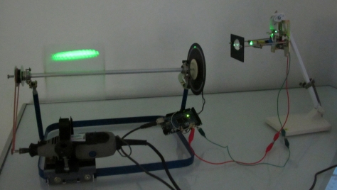
Fig.22 – Zeppelin model appearing on display
Special thanks and honorable mentions
Many thanks to the Computer Graphics staff at the TU Berlin, for Inviting, teaching, consulting and
encouraging.
Prof. Dr. Bernd Bickel / Chair of Computer Graphics, Technische Universität (TU) Berlin
Kristian Hildebrand / Computer Graphics, Technische Universität (TU) Berlin
To the electronic genius.
Arthur Roth / Technical University (TU) Berlin
To my dear friends from the Berlin creative communities.
Jay Cousins / Open Design City (ODC) Berlin / CeBIT 2012
Pedro Pineda / We Creative People / CeBIT 2012
Michel David
2012
Download full article (PDF): New_Approach_to_Volumetric_displays

Pingback: Volumetric display looks like a DaVinci sketch - Hack a Day
Pingback: Volumetric display looks like a DaVinci sketch » Geko Geek
Pingback: Homemade Volumetric Display « adafruit industries blog
Pingback: MAKE | Hacktastic Horizontal Helical 3D Display
Pingback: Hacktastic Horizontal Helical 3D Display | Indoor Digital Billboards
Pingback: Hacktastic Horizontal Helical 3D Display
Pingback: Laser Phase Blog » Blog Archive » Volumetric laser display
It is rare for me to uncover something on the web thats as entertaining and intriguing as what you have got here. Your page is sweet, your graphics are great, and whats much more, you use source that are relevant to what youre saying. That you are undoubtedly one in a million, well done! bbgadcbedkde
Great project. You should however consider a model without so many identical cross sections (circles), to really highlight its ability to show distinct profiles at different depths.
Pingback: Class Development4 – Congjia &